Binary Adder Subtractor Circuit
Adder logisim bit circuit binary Adder bit subtractor binary circuit circuitlab description Adder bit subtractor circuit diagram block using logic draw
Adder-Subtractor | VLSI & Embedded Projects
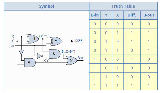
Adder subtractor binary logic combinational sub subtraction adders Adder subtractor Adder subtractor circuit subtraction circuits
Binary adders and subtractors
Solved considering the binary adder subtractor circuitBinary adders and subtractors Digital logicCircuit adder subtractor bit using subtraction logic carry sub digital borrow input control additional signal add now standard then stack.
Figure 2 from a novel approach for reversible realization of 8-bitBinary adder-subtractor circuit. Digital logicBinary adder/subtractor.

Subtractor adder solved answer problem
Binary addersLet's learn computing: 4 bit adder/subtractor circuit Subtractor truth electronics electronicspostAdder subtractor bit vhdl input subtract output allaboutfpga.
Vhdl code for 4-bit adder / subtractor2-bit binary adder/subtractor Adder subtractor binary vhdlBinary subtractor – electronics post.

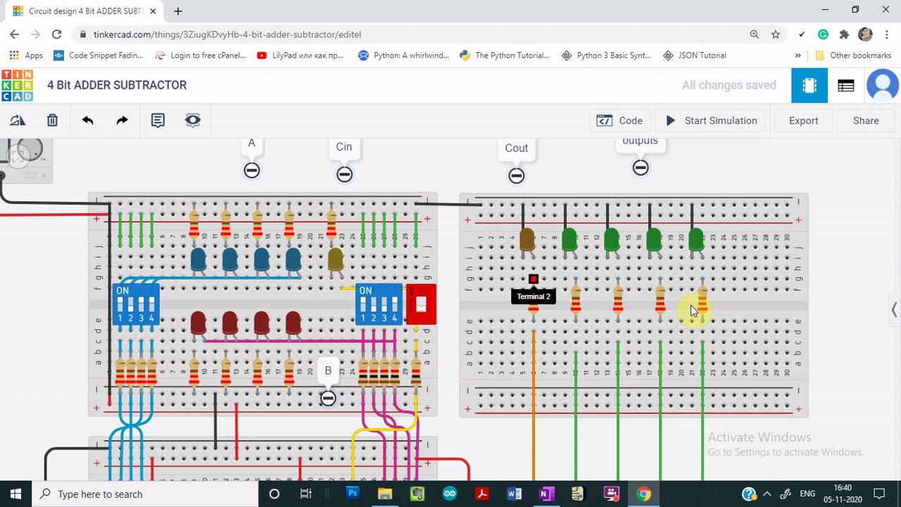
Demo: 4-bit adder subtractor using full adder ic with tinkercad
Solved consider the 4-bit adder/subtractor circuit displayedAdder bit subtractor circuit values following consider input mode has help steps solve thank solved questions Subtractor adder binary circuit discussionBinary adder and subtraction circuits along with its various types.
Make adder subtractor bit carry ripple verilog binary using 4bit want subtraction addition operation output hdl which has valueAdder subtractor bit circuit add sub questions overflow complement logic detection carry addition designing control zero digital line find Draw the logic diagram of a full adder. create a 2-bit adder-subtractorAdder subtractor tinkercad.

Adder subtractor vlsi
N-bit binary adder circuit by logisimSubtractor adder realization reversible quantum 4-bit binary adder-subtractorBinary subtractor adders.
Logic adder subtractor parallel binary circuit bit diagram mode control signal digital determines which hasSubtractor binary adder screenshots runs Digital logicBinary adder/subtractor.
Adder bit subtractor circuit ripple carry logic diagram using project build only digital computing learn let its single indie electronics
Digital logic design: binary parallel adder/subtractorAdder subtractor binary circuit bit diagram coa logic block javatpoint mode Lesson 13 binary adder subtractor in vhdlAdder parallel bit logic subtractor four digital circuit binary diagram block addition carry example geeksforgeeks detailed discussion.
4 bit binary adder subtractor pdf .


Draw the logic diagram of a full adder. Create a 2-bit adder-subtractor

Solved Consider the 4-bit adder/subtractor circuit displayed | Chegg.com

Adder-Subtractor | VLSI & Embedded Projects

Binary Adders and Subtractors

COA | Binary Adder-Subtractor - javatpoint

Digital Logic | Parallel Adder & Parallel Subtractor - GeeksforGeeks
Binary Subtractor – Electronics Post